3D from Scratch - Day 2
This is my attempt to figure out enough 3D graphics from scratch to clone the original Elite. The start of the series is here: 3D from Scratch - Intro.
Weird Cube Bug
When I presented Day 1 at our work Breakfast Club this week, the first thing someone did is grab the controls and instantly find a bug. 😠
Here it is: if you move the cube directly towards the camera, at some point you see strange lines that cross the screen. And then if you keep moving the cube back, it reappears moving forward from again!
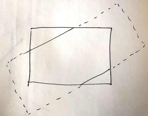
So first I removed all but one edge of the cube, to get a clearer idea whats happening:
And it seems that the points are transposed to the position that they would be in if I turned around, and turned upside down.
I think the lines that unaccountably cross the screen are just an artefact of this – when one point is in normal view and one point is in upside-down-reverse view it still tries to draw a line between them.
That means I can remove all but one point to debug it:

My normal debugging strategy at this point is to add a shit-ton of logging to everything, but first let’s just look at the point drawing code and think about what it might be:
function drawPoint3d(ctx, p) {
  var x = Math.round(p.x * (screen_dist / p.z))
  var y = Math.round(p.y * (screen_dist / p.z))
  setPixel(ctx, x + PIXEL_WIDTH/2, y + PIXEL_HEIGHT/2)
}
First thing to notice is that p.z will turn negative when the point comes towards the camera and then passes it. That will make x and y negative too. The x value is then subtracted from PIXEL_WIDTH/2 rather than added to it, which is why it appears reversed! Solved!
So the obvious thing to do is to add a guard that just bails on drawing the point if p.z is negative. That would probably work here, but in general it is quite possible to have one end of a line be behind the camera, and the other end in front of it, and still want to draw the line.
Also, the criteria as to whether a point is drawn or not is not actually whether it’s behind the camera, but whether it’s inside the camera’s view of the screen, and a point leaves that field of view well before p.z turns negative.
So to do this right I’ll have to figure out what appears in the field of view of the camera.
This has turned into a larger task than I was expecting.
Task: Don’t display things not in the camera’s field of view
I knew this was going to be an issue eventually, so might as well get right into it. This was a bit tricky to figure out, I had to break out the old Maths textbooks and everything.
How to decide whether the camera can see something? Here are two diagrams I drew while thinking about this.
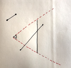
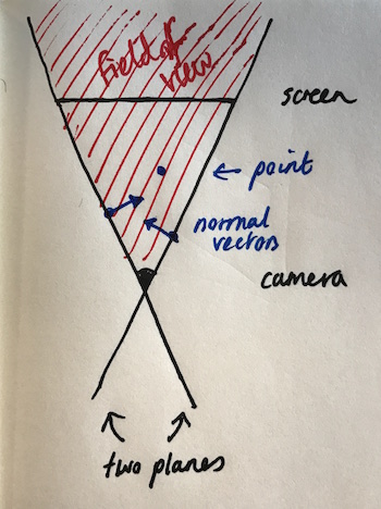
This one depicts a side view of the camera and screen, with two lines that do or do not appear in view:
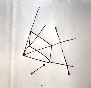
This one is my attempt to draw the camera, screen and field of view in 3d, again with one line that is not visible and one that is, partially:
After half an hour of staring at these diagrams, here are the observations I made:
- the field of view of the camera is a pyramid, with the apex centred on the camera. This space is defined as the interior of the shape formed by 4 planes, each of which contain the camera and two (different) corners of the screen.
- a point is visible if it is on the inside of all four planes
- a line with both points inside the field of view is entirely visible
- a line with both points outside the field of view may still be partially visible if it intersects the field of view (the second line in both diagrams)
- it’s fairly easy to tell which side of a plane a point lies on, using Maths… so for any point you can tell if it is inside the field of view by checking it against the four planes and seeing if it is inside all of them.
Now practically you could exclude from drawing any line that doesn’t have both ends inside the field of view. This is tempting as most things will be composed of many fairly short lines, and it is not common to fly right into things…
But this is not good enough in the long run, as there are real world cases where a line might cross the vision and you still want to draw it… for instance you might be docking with a space station and only be able to see part of the docking port:
Subtask: don’t draw a line with either end offscreen
However, it’s a good first step, so that’s what I’m going to focus on first. (Only drawing a line if both ends are inside the field of view.)
Here’s where it gets mathsy. I had to look a bunch of this up but it’s all coming back to me now. Maths concepts, with code:
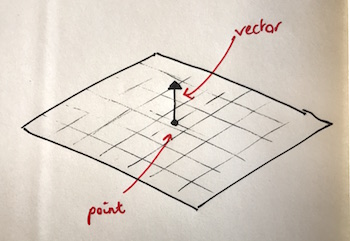
A plane. A plane can be defined as a single point (which is in that plane) and a single “normal” vector, which is perpendicular to the plane. There are infinite points and vectors which work for this, so we will pick ones that make things easy for us.
Dot product. This is the sort-of multiplication of two vectors to give a single number. It shows sort-of “how much in the same direction they are but multiplied”. Vectors at right angles have a zero dot product, and as will become important in a moment, if two vectors are in opposite directions the dot product is negative. It’s written as n•v if n and v are vectors.
// u and v are vectors with x,y,z components
function dot(u, v) {
  return u[0]*v[0] + u[1]*v[1] + u[2]*v[2]
}
Cross product. Taking the cross product of two vectors gives you another vector that is at right angles to the plane formed by them.
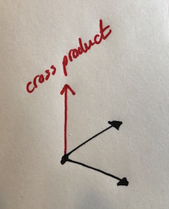
It’s defined like this, don’t ask me why:
function cross(u, v) {
  return [
    u[1]*v[2] - u[2]*v[1],
    u[2]*v[0] - u[0]*v[2],
    u[0]*v[1] - u[1]*v[0],
  ]
}
Now here’s the plan. We’re going to:
- find normal vectors for the four planes that define the field of view, and in particular, they’re going to be normal vectors that point “inwards” towards the field of view, not ones that point “outwards”.
- each normal vector will be calculated by taking the cross product of two vectors that we know are in the plane. In this case, that’s the two vectors from the camera to the corners of the screen.
- for any point we care about, check which side of each of the four planes it is on.
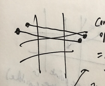
This is pictured in top-down view here (with only the two side planes):
How do we tell which side of the planes the point is on? Well, this is what the dot product is for. Look at this next diagram. p and q are the normal vectors of the two planes. The vector a is to a point that is in view, and the vector b is to a point that is not.
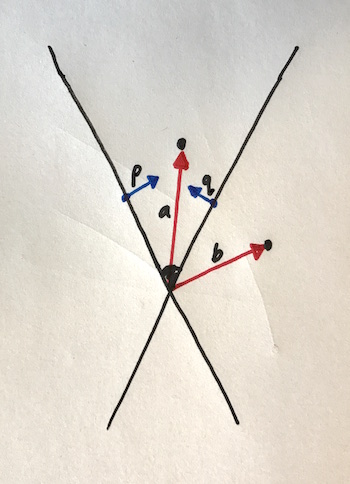
The dot product of a with p will be positive, as they are both pointing inwards from the left plane. Same for q. So since the dot products are both positive, we know the point at a is in view.
The dot product of b with p will also be positive BUT the dot product of b with q is negative, as b and q are pointing different ways away from the plane on the right.
So you can see, if we take the dot products of the point with each of the four normals, we need them all to be positive to know that the point is in view.
Let’s code that up. Here are the coordinates of the four corners of the screen:
// clockwise from bottom right
var screen_coords = [
  [ PIXEL_WIDTH/2,  PIXEL_HEIGHT/2, screen_dist],
  [-PIXEL_WIDTH/2,  PIXEL_HEIGHT/2, screen_dist], // bottom left
  [-PIXEL_WIDTH/2, -PIXEL_HEIGHT/2, screen_dist], // top left
  [ PIXEL_WIDTH/2, -PIXEL_HEIGHT/2, screen_dist], // top right
]
And here are the inward-pointing normals. This is done by taking the cross product of two vectors in each plane to get a new vector at right angles to both of them, and because the camera is at (0,0,0) the points at the corners represent vectors straightaway. (I actually did these in the opposite order first, and that produced outward-pointing normals – once I noticed it was the wrong way round I just flipped the order):
var view_plane_normals = [
  cross(screen_coords[0], screen_coords[1]), // bottom plane
  cross(screen_coords[1], screen_coords[2]), // left plane
  cross(screen_coords[2], screen_coords[3]), // top plane
  cross(screen_coords[3], screen_coords[0]), // right plane
]
Now the code that actually checks if a point is in view. All it does is check that the dot product of the point with each normal is positive, as we discussed before:
function isPointInView(p) {
  for (var i = 0; i < view_plane_normals.length; i++)
    if (dot([p.x, p.y, p.z], view_plane_normals[i]) < 0)
      return false
  return true
}
And now we can adjust drawFrame to not draw any line where both points are not in view:
  ...
  if (isPointInView(newP1) && isPointInView(newP2))
    drawLine3d(ctx, newP1, newP2)
  ...
And run it:

And that looks much better! Our weird bug is fixed, and you can see it is correctly removing any line with an end offscreen.
Subtask: Draw the part of the line that appears onscreen
However, you can now see that we are having lines disappear when they should still be partially visible. This means that when we have a line that has one or both ends offscreen, we should figure out exactly what part of it is visible and draw that.
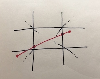
It’s clear that we’re going to need a way to compute the intersection of a line with a plane, to be able to figure out exactly the point on the edge of the view to draw the lines from and to. For instance, in this diagram the line goes across the view so we need to know the two intersection points with the left and right side of the view:
So first let’s figure out how to do that. /Daunting
Every so often in this series, I’m going to say something like “and then I sat and stared into space for three solid hours”. This is one of those times.
Here’s what I came up with.
Representation of the line. What we have is two points p = (a,b,c) and q = (d,e,f) that are the start and the end of the line (these are the corners of the cube). The line runs from one point to the other. So the representation of the line is as the three equations:
- x = a + t(d-a),
- y = b + t(e-b),
- z = c + t(f-c).
This is called the parametric representation. t runs from zero to one and is “the proportion we are along from one end to the other”. To see that these are the right equations, notice how when t = 0 that x, y and z are just a, b and c, and when t = 1 they are d, e, f. So the ends are right. And since the equations are linear they describe a straight line, no curving going on. So if the ends are right and the line is straight this must be the right equations.
Representation of the plane. Now, there are three ways to represent a plane. One is the normal vector and point representation we already discussed. One is a parametric representation, but using three points in the plane and two variables instead of one. And one is the equation of the plane: ax + by + cz = d
Now I could see how to find the intersection point by plugging the equations of the parametric representation of the line into the equation of the plane.
However, we don’t actually have the equation of the plane. What we have is the parametric representation. And blowed if I could figure out how to go from one to the other.
I’m afraid I had to look this up (I’m allowed to look up maths, though I’m trying not to). Once I had, it seems so obvious and I’m a bit annoyed at myself for not figuring this out.
We actually have two representations of the plane already, the parametric representation and the normal & point representation. And going from the normal & point representation to the equation of the plane is really easy.
What does every vector in the plane have in common? They are all at right angles to the plane’s normal vector. And we said earlier that the dot product of two vectors at right angles is zero. Therefore, if v is a vector in the plane, and n is the plane normal, n•v = 0.
From this we can get the equation of the plane. Let’s pick a point in the plane p = (a, b, c). For all points q = (x, y, z), the vector q - p is in the plane if and only if n •(q-p) = 0. If n=(n,m,o) then by the definition of the dot product this gives us an equation of the plane n(x-a) + m(y-b) + o(z-c) = 0
This is even easier in our case, because the camera is in all our planes, and the camera is at (0,0,0), we can just use that point as our p and the equation is just nx + my + oz = 0.
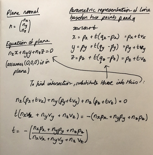
So now we can work out an formula for t that we can use to give us the intersection point of a line and a plane, by substituting the parametric representation of the line into the equation of the plane. Here’s my derivation, with different constant names:
And here’s the code for it:
// takes two points that define a line and a plane normal
// and returns where the line intersects the plane
// (assumes (0,0,0) is in the plane)
  function linePlaneIntersection(p, q, n) {
    var v = [q.x - p.x, q.y - p.y, q.z - p.z]
    var t = -1*(n[0]*p.x + n[1]*p.y + n[2]*p.z) /
               (n[0]*v[0] + n[1]*v[1] + n[2]*v[2])
    if (t < 0 || t > 1)
      return null
    return {x: p.x + t*v[0], y: p.y + t*v[1], z: p.z + t*v[2]}
  }
Clamping the line to the view
Ok! Now we know how to compute intersections, we are very close to being able to truncate the lines by finding their intersection points with the viewplanes! Problem is, how do we know which planes to compute the intersections of the line with?
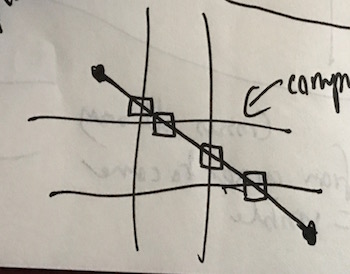
There are quite a few cases here depending on where the line starts and finishes, and indeed I spent quite a long time drawing lines across squares to try to figure out a neat way of figuring out exactly which planes the lines will intersect with.
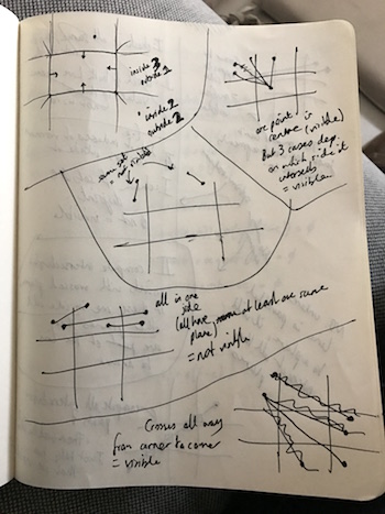
This went nowhere, because of the case where the line goes from the top offscreen to the side offscreen. This might or might not intersect the view depending on the exact start and end points:
So then I thought, let’s just brute force it: for any line, collect all the points of intersection with the planes that define the view, and then just pick whichever two are visible (a point on the exact edge of the view we’ll define as visible). And if none are visible, then the line doesn’t intersect the view.
And if one end of the line is visible to begin with, then you only need one of those points of intersection to be visible.
So, that gives us a plan, and we can code it up. This function returns false if none of the line is visible, and otherwise returns the two points that define the part of the line that is visible:
// Returns false if the line between p and q is not
// visible at all. If it is, returns the points for the
// part of the line that is visible.
function clampLineToView(p, q) {
  var p_in = isPointInView(p)
  var q_in = isPointInView(q)

  // if both visible, we're done
  if (p_in && q_in)
    return [p, q]

  // we need two visible endpoints. Include p or q
  // if either of them is visible
  var visible_a = p_in ? p : (q_in ? q : null)
  var visible_b = null

  // now find the intersections and keep going until we
  // have two visible points
  for (var i = 0; i < view_plane_normals.length; i++) {
    var ip = linePlaneIntersection(p, q, view_plane_normals[i])
    if (ip && isPointInView(ip)) {
      if (visible_a == null) {
        visible_a = ip
      } else if (visible_b == null) {
        visible_b = ip
        break
      }
    }
  }

  // if we have found two visible points, return them,
  // otherwise return false, meaning none of the line
  // is visible.
  if (visible_a != null && visible_b != null)
    return [visible_a, visible_b]
  else
    return false
}
To demo this I’ve done a few things. First I moved the edges of the view inwards a few pixels so we can see the lines vanish (otherwise I’d never be sure if it wasn’t getting the visible portion wrong but just drawing it off canvas):
// clockwise from bottom right
var screen_coords = [
  [ PIXEL_WIDTH/2 - 15,  PIXEL_HEIGHT/2 - 15, screen_dist], // bottom rt
  [-PIXEL_WIDTH/2 + 15,  PIXEL_HEIGHT/2 - 15, screen_dist], // bottom left
  [-PIXEL_WIDTH/2 + 15, -PIXEL_HEIGHT/2 + 15, screen_dist], // top left
  [ PIXEL_WIDTH/2 - 15, -PIXEL_HEIGHT/2 + 15, screen_dist], // top right
]
Then change drawFrame again to only draw the right part of the line, and to draw the intersection points too so we can see it clearly:
  …
  // draw edges
  for (var j = 0; j < edges.length; j++) {
    var p1 = cube[edges[j][0]]
    var p2 = cube[edges[j][1]]
    var newP1 = {x: p1.x + transform.x, y: p1.y + transform.y, z: p1.z + transform.z}
    var newP2 = {x: p2.x + transform.x, y: p2.y + transform.y, z: p2.z + transform.z}

    var clampedLine = clampLineToView(newP1, newP2)
    if (clampedLine) {
      ctx.fillStyle = "blue"
      drawLine3d(ctx, clampedLine[0], clampedLine[1])

      ctx.fillStyle = "red"
      drawPoint3d(ctx, clampedLine[0])
      drawPoint3d(ctx, clampedLine[1])
    }
  }
  …
And now to run it and see…
And that shows clearly that the lines are being truncated only to the visible portion!
Bug: flickering lines
However, we do have a bug here. The truncated lines sometimes flicker as they move. I made another video so it was clear:
This is very strange.
The debugging process was to remove all but one line, and add logging extensively until it became clear what was going on.
If you open up the JavaScript console and run this calculation:
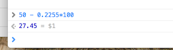
there’s a chance that instead of getting 27.45 as your answer, you’ll in fact get 27.4500000000003. This is because floating point calculations that look as though they should be precise to us humans can have drift due to representational inaccuracies. In fact on my other laptop this was happening consistently, but not here, so I guess it’s due to system specific stuff exactly when this happens.
The problem is that our isPointInView function compares the value of the dot product against 0. And the intersection points we’ve been calculating are actually on the planes in question, so the dot product is often exactly 0 when this function is called. So a slight inaccuracy in the value of the coordinate is enough to render the point not visible when it is in fact on the plane.
The line flickers because this inaccuracy only occurs some of the time, again based on system specific factors.
There’s probably a better way of doing this, but I’ve fixed it by adding a fudge factor to the comparison in isPointOfView:
function isPointInView(p) {
  for (var i = 0; i < view_plane_normals.length; i++)
    if (dot([p.x, p.y, p.z], view_plane_normals[i]) < -0.001)
      return false
  return true
}
And the result, no flickering!
Conclusion
Now I’ve got this all working, I’ve removed the extra space, and the drawing of the intersection and corner points to show what we should really see:
And that’s it! This looks very similar to yesterday’s final demo, and indeed if the cube stays within the view it is identical. But although you can’t see it, it is properly not drawing lines that it can’t see.
So, there are two things that still bug me about todays work:
- computing the intersection of every line with every plane. If we assume there are going to be many many lines in the simulation, this might add up to a lot of work. I have an idea how to optimize this if need be though.
- the assumption that the camera is at (0,0,0). This has been very handy but I’m starting to suspect that we’re going to have to move the camera eventually (as opposed to moving the entire rest of the world), which means revisiting some of these formulae.
But, for now, it’s all working, so let’s press on and come back to these when we have to!
On to Day Three…